A Geared Electric Motor combines an electric motor with a gearbox to deliver controlled mechanical motion. The motor creates rotational force, while the gears adjust speed, torque, and direction. This arrangement appears in conveyor systems, electric gates, mixers, medical equipment, and small industrial machines. It is not simply a stronger motor. The gearbox changes how power reaches the driven shaft.
At first glance, the operating principle seems straightforward. Electrical energy enters the motor, producing a rotating magnetic field. That field turns the rotor and its output shaft. The gearbox then transfers this rotation through meshing gears. Smaller driving gears can produce slower output with greater torque. Larger output gears can reverse that relationship. Real performance depends on gear ratio, motor design, load, lubrication, alignment, and duty cycle. Small details matter.
This guide explains what happens inside a Geared Electric Motor and why engineers select one design over another. It also considers efficiency, noise, heat, maintenance, and practical sizing. In field installations, a motor may run well without carrying the correct load. That can hide a serious sizing error. A rough calculation is not enough. Readers should compare manufacturer data with actual operating conditions, including starting force and repeated stops. Some explanations oversimplify gear losses. They deserve a closer look. Understanding those limits helps technicians choose safer, more reliable, and longer-lasting drive systems.
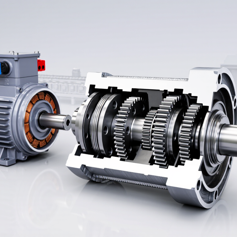
A geared electric motor combines four working parts: the motor, gearbox, output shaft, and housing. The motor creates rotational speed and torque. The gearbox reduces speed while increasing usable torque at the output shaft. For example, a motor spinning at 1,800 revolutions per minute may deliver a much slower, stronger rotation after reduction. That change helps conveyors, mixers, gates, and lifting mechanisms move controlled loads.
The housing holds the assembly in alignment and protects gears from dust, impact, and accidental contact. Inside, gear teeth transfer force through several stages. Helical gears usually operate more quietly than straight-cut gears, although they create additional axial loads. Engineers therefore check bearing capacity, lubrication, thermal limits, and shaft deflection. A small mistake matters. Poor alignment can create vibration, noise, and early tooth wear.
The International Energy Agency reported that electric motor systems consume about 53% of global electricity. This figure explains why efficient motor selection deserves careful attention. The U.S. Department of Energy also identifies system-level improvements, including proper sizing and controls, as significant energy-saving opportunities. Efficiency is not only a motor rating. Gearbox losses, lubricant condition, load patterns, and starting frequency all influence real performance. IEC 60034-1 supports motor performance classification, while ISO 6336 provides methods for evaluating cylindrical gear strength. These standards guide reliable design, but field conditions can still differ from laboratory assumptions. Check the actual load.
| Category | Element or Parameter | Definition or Typical Data | Function and Practical Notes |
|---|---|---|---|
| Basic Definition | Geared Electric Motor | An electric motor integrated with a reduction gearbox to provide lower rotational speed and higher usable torque. | The motor supplies mechanical power, while the gearbox changes speed and torque to better match the driven load. |
| Main Component | Electric Motor | Converts electrical energy into rotational mechanical energy. Common motor technologies include induction, permanent-magnet, brushed DC, and brushless DC motors. | Its rated voltage, current, power, speed, and duty cycle must be compatible with the power supply and application. |
| Main Component | Gearbox | A mechanical transmission containing meshing gears that reduces speed and transfers torque from the motor to the output shaft. | Gearbox design affects reduction ratio, efficiency, noise, backlash, load capacity, and service life. |
| Main Component | Output Shaft | The rotating shaft that delivers the gearbox output to the driven machine or mechanism. | Important specifications include output speed, continuous and peak torque, shaft diameter, mounting arrangement, and allowable radial or axial load. |
| Main Component | Housing | The enclosure that supports the motor and gearbox components and protects them from mechanical contact and environmental exposure. | The housing may also provide heat dissipation, mounting points, alignment, sealing, and structural rigidity. |
| Operating Principle | Energy Conversion Sequence | Electrical input → electromagnetic force in the motor → motor shaft rotation → gear engagement → reduced-speed output rotation. | The gearbox does not create energy; it trades rotational speed for torque while introducing mechanical losses. |
| Performance | Gear Reduction Ratio | Ratio = input speed ÷ output speed. For example, a 20:1 ratio reduces an input speed of 1,400 rpm to approximately 70 rpm before considering slip or load effects. | Higher ratios generally produce lower output speed and greater output torque, but may increase size, losses, and backlash. |
| Performance | Output Speed | Approximate output speed = motor speed ÷ reduction ratio. | Actual speed can vary with motor slip, controller settings, voltage, frequency, and load. |
| Performance | Output Torque | Approximate output torque = motor torque × reduction ratio × gearbox efficiency. | Torque must be checked for continuous operation, acceleration, starting, shock loads, and temporary peak conditions. |
| Performance | Mechanical Power | Power is related to torque and speed by P = T × ω. In practical units, power in watts is approximately torque in newton-metres × angular speed in radians per second. | Ignoring losses, reducing speed increases torque while keeping mechanical power approximately constant. |
| Gearbox Types | Spur or Helical Gearbox | Uses parallel-axis gears. Helical teeth generally provide smoother and quieter engagement than straight spur teeth. | Suitable for many general-purpose applications; helical designs can generate additional axial forces. |
| Gearbox Types | Planetary Gearbox | Uses a sun gear, planet gears, and a ring gear arranged around a central axis. | Offers high torque density, good load sharing, and compact dimensions, but usually has greater design complexity. |
| Gearbox Types | Worm Gearbox | Uses a worm screw and worm wheel to transmit motion between typically non-parallel shafts. | Can provide high reduction in a compact arrangement; efficiency and back-driving behavior depend strongly on geometry, lubrication, and load. |
| Key Ratings | Voltage and Frequency | Electrical supply requirements stated by the motor design, such as direct-current voltage or alternating-current voltage and frequency. | Incorrect voltage or frequency can cause overheating, poor starting performance, unstable speed, or insulation damage. |
| Key Ratings | Duty Cycle | Describes how the motor operates over time, such as continuous running, intermittent operation, or repeated starts and stops. | The selected motor must withstand the thermal load created by the complete operating cycle, not only the average load. |
| Key Ratings | Efficiency | Overall efficiency is the ratio of mechanical output power to electrical input power and includes motor and gearbox losses. | Efficiency changes with speed, torque, temperature, lubrication, alignment, and operating point. |
| Mechanical Factors | Backlash | The small amount of lost motion caused by clearance between mating gear teeth. | Low backlash is important for positioning, indexing, and reversing applications; some clearance is necessary for lubrication and thermal expansion. |
| Mechanical Factors | Allowable Shaft Loads | Permitted radial and axial forces on the output shaft, determined by bearings, shaft design, speed, and mounting conditions. | External loads above the specified limits can shorten bearing life or cause shaft and gear failure. |
| Thermal Management | Heat Dissipation | Heat is generated by electrical resistance, magnetic losses, bearing friction, gear friction, and windage. | Adequate airflow, correct mounting, appropriate load, and clean cooling surfaces help prevent excessive temperature rise. |
| Maintenance | Lubrication and Inspection | Maintenance may include checking lubricant condition, seals, fasteners, alignment, vibration, noise, temperature, and electrical connections. | Use only the lubricant and maintenance interval specified for the gearbox design; sealed units may not require routine relubrication. |
| Typical Applications | Motion and Drive Systems | Conveyors, actuators, gates, packaging equipment, material-handling systems, pumps, mixers, adjustable mechanisms, and automated machinery. | Geared motors are useful when a direct-drive motor would run too fast or produce insufficient torque for the required load. |
The motor creates rotation. The gearbox reduces speed and increases usable torque. This suits conveyors, feeders, platforms, and compact automation equipment.
Match the motor voltage to the available supply. Common options include 24 VDC, 48 VDC, and 230 VAC. Wrong voltage may cause weak starting or permanent damage.
Consider load torque, speed, friction, and acceleration. Include the starting load, not only normal running conditions. A loaded conveyor may need much more torque at startup. My first estimate failed because I ignored belt tension.
Duty cycle describes running and resting periods. Continuous operation requires strong thermal capacity. Short movements may allow a smaller motor. Frequent starts can still create serious heat.
IP54 may suit a clean indoor workshop. Washdown areas usually need stronger protection. Check spray direction, cleaning methods, cable glands, shafts, and joints. Ratings are not magic.
Proper lubrication reduces friction between gears, bearings, and shafts. Use the specified lubricant and amount. Too little lubricant increases heat and wear. Too much may create drag, pressure, or seal problems. Sealed gearboxes may need no relubrication.
Listen for clicking, grinding, or a rising pitch. These sounds may indicate worn gears, loose bolts, poor alignment, or damaged bearings. Check for leaks, metal particles, dark grease, or a burnt smell. A quiet motor is not always healthy.
Avoid repeated overloads and keep the motor dry. Mount it correctly and maintain proper alignment. Monitor temperature, sound, and vibration over time. One brief temperature check can miss a developing fault. Small records help.
A Geared Electric Motor combines an electric motor, gearbox, output shaft, and protective housing to deliver controlled mechanical motion. The gearbox adjusts torque and speed according to its ratio, with common reductions ranging from 3:1 to 300:1. Higher ratios generally provide greater output torque and lower speed, making the motor suitable for applications that require steady, powerful movement. Performance depends on the design, load, and operating conditions, with typical efficiency ranging from 70% to 95% and load capacity varying by motor size and gear construction.
When selecting a Geared Electric Motor, consider the required voltage, power rating, duty cycle, operating environment, and appropriate IP protection level. These motors are widely used in conveyors, actuators, machinery, automation systems, and positioning equipment. Regular lubrication can reduce friction and wear, while noise levels depend on gear type, alignment, load, and operating speed. Proper installation, cooling, maintenance, and avoidance of overloads can significantly improve service life and reliability.

 Viterra Motor